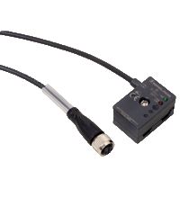

VBA-4E4A-KE5-ZEJQ/E2L
22861 ₽
Параметры
| Входы питания | Внутренний (от AS-i) |
|---|---|
| Выходы питания | Внешний (от AUX) |
| Выходы модуля | 4 |
| Стиль корпуса | KE5 |
| Место монтажа | Монтаж в корпус |
| Входы модуля | 4 |
| Тип модуля | Цифровые I/O |
| Подключение I/O | Клеммники |
| Тип узла | A/B узел |
Технические характеристики
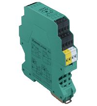
The AS-Interface connecting module VBA-4E4A-KE5-ZEJQ/E2L is a switch cabinet module with 4 inputs and 4 electronic outputs. The housing is only 19 mm wide and takes up little space in the switch cabinet. The module is mounted by snapping onto the 35 mm DIN rail in compliance with EN 50022.
The connection is made via removable 4-pin push-in terminal blocks. For AS-i+, AS-i-, AUX+, and AUX-, two connections are available in each case; these connections are bridged in the terminal block. If the terminal block is disconnected from the module, the link between these connections is retained. The terminal blocks for the inputs and outputs are mechanically coded.
The supply to the inputs and the connected sensors can be fed either from the internal supply of the module from the AS-Interface or via an external UEXT voltage source. A switch located on the side of the module changes the source.
The internal input supply is displayed via the INT LED. The relevant IN and OUT LEDs display the current switching status of the inputs and outputs. The OUT LEDs also indicate an overload or a lead breakage at the corresponding output.
Safety Applications
The module offers safe galvanic isolation between the output part supplied by AUX and the other circuit components. As such, it can be used in applications that require reliable switch-off of the AUX power supply for EMERGENCY STOP functions up to safety classification PLd via an external switching element. Details of the conditions that apply in this case can be found in the «Notes» section of the original instructions.
Notes:
The device is equipped with a communication monitor, which deactivates the outputs if the AS-Interface does not communicate with the module for more than 40 ms. The communication monitor can be deactivated via the parameter P0. Filters that suppress pulses with a duration of 2 ms or less at the inputs can be connected via the parameter P1.
Parameter P2 activates a lead breakage detection system for the outputs. This function detects and reports a missing load, providing the relevant output is deactivated. The associated OUT LED provides a visual indication of the missing load, and the ‘peripheral fault’ function reports it to the AS-Interface master. A signal indicating an overload of the internal input supply or the outputs is also transmitted to the AS-Interface master via the ‘peripheral fault’ function. Communication via the AS-Interface continues even if a peripheral fault is set.
| Описание продукта |
|---|
| Cabinet module 4 inputs and 4 outputs |
| Основные Характеристики | ||
|---|---|---|
| Node type | Узел A/B | |
| Спецификация AS-интерфейса | В3.0 | |
| Требуемая спецификация шлюза | ≥ V3.0 | |
| UL File Number | E223772 | |
| MTBF | 141 а | |
| Индикаторы/средства управления | ||
| СВЕТОДИОДНАЯ НЕИСПРАВНОСТЬ | Error display; red LED red: communication error, i.e. address is 0 red flashing: overload internal input supply, i.e. overload or lead interruption outputs |
|
| СВЕТОДИОД ВНУТРЕННИЙ | Внутреннее входное питание активно; светодиод зелёный. | |
| LED PWR | AS-Interface voltage; green LED green: voltage OK flashing green: address 0 |
|
| Светодиод AUX | ext. auxiliary voltage UAUX; dual LED green/red green: voltage OK red: reverse voltage |
|
| LED IN | Состояние переключения (вход); 4 светодиода жёлтого цвета | |
| LED OUT | switching state (output); 4 LED yellow/red yellow: output active red: output overload or lead interruption |
|
| Электрические характеристики | ||
| Вспомогательное напряжение (вход) | 12 … 30 В DC PELV | |
| Вспомогательное напряжение (выход) | 20 … 30 В DC PELV | |
| Номинальное рабочее напряжение | 26,5 … 31,6 В от AS-Interface | |
| Номинальный рабочий ток | ≤ 35 мА (без датчиков) / макс. 190 мА | |
| Класс защиты | Класс защиты | |
| Защита от перегрузки | UEXT, UAUX, Ue: overvoltage category II, safe isolated power supplies (PELV) Overvoltage category of the power supplies (primary): III |
|
| Номинальное напряжение изоляции | 92 В | |
| Импульсное напряжение выдержки | 0,8 кВ | |
| Вход | ||
| Номер/Тип | 4 входа для 3-проводных датчиков (PNP), DC | |
| Питание | from AS-Interface (switch position INT, default settings) or external UEXT (switch position EXT) | |
| Напряжение | 21 … 31 В DC (INT) | |
| Текущая нагрузочная способность | ≤ 150 мА, с защитой от перегрузки и короткого замыкания (INT) | |
| Входной ток | ≤ 5,6 мА (макс.) | |
| Точка переключения | в соответствии с DIN EN 61131-2 (тип 1) | |
| 0 (неослабленный) | ≤ 0,5 мА | |
| 1 (ослабленный) | ≥ 2 мА | |
| Задержка сигнала | < 1 мс (вход/AS-Interface) | |
| Выход | ||
| Номер/Тип | 4 электронных выхода, PNP, защита от перегрузки и короткого замыкания | |
| Питание | from external auxiliary voltage UAUX | |
| Напряжение | ≥ (UAUX — 0.5 V) | |
| Ток | 2 A Per output, total 4 A (TB ≤ 60 °C) 1 A Per output, total 4 A (TB ≤ 70 °C) |
|
| Категория использования | DC-13 | |
| Соответствие директивам | ||
| Электромагнитная совместимость | ||
| Directive 2014/30/EU | EN 62026-2:2013 EN 61000-6-2:2005, EN 61000-6-4:2007 | |
| Директива по машиностроению | ||
| Директива 2006/42/EC | EN ISO 13849-1:2008 EN ISO 13849-2:2012 | |
| Стандарты соответствия | ||
| Степень защиты | EN 60529:2000 | |
| Стандарт Fieldbus | EN 62026-2:2013 | |
| Электробезопасность | IEC 61140:2009 — Электробезопасность | |
| Вход | EN 61131-2:2004 | |
| Излучаемые помехи | EN 61000-6-4:2007 | |
| AS-Интерфейс | EN 62026-2:2013 | |
| Помехоустойчивость | EN 61000-6-2:2005, EN 61326-1:2006, EN 62026-2:2013 | |
| Функциональная безопасность | EN ISO 13849-1:2008 EN ISO 13849-2:2012 | |
| Инструкции по программированию | ||
| Профиль | Профиль | |
| Код ввода-вывода | 7 | |
| Код ID | A | |
| Код ID1 | 7 | |
| Код ID2 | 7 | |
| Биты данных (функция через AS-Interface) | ||
| D0 | ||
| Параметр ‘Инструкции по программированию’, Категория ‘<tab> </tab>IN2’. | ||
| Параметр ‘Инструкции по программированию’, Категория ‘<tab> </tab>IN3’. | ||
| D3 | ||
| Параметры биты (программируемые через AS-i) | function | |
| P0: Программные инструкции, Категория: не используется. | Communication monitoring P0 = 0 monitoring = off, the outputs maintain the status if communication fails P0 = 1 monitoring = on, i.e. if communication fails, the outputs are deenergised (default settings) |
|
| Параметр ‘Инструкции по программированию’, Категория ‘Фильтр входного сигнала<br/>P1 = 0 фильтр входного сигнала включен, подавление импульсов ≤ 2 мс<br/>P1 = 1 фильтр входного сигнала выключен (настройки по умолчанию)’. | Input filter P1 = 0 input filter on, pulse suppression ≤ 2 ms P1 = 1 input filter off (default settings) |
|
| Категория: Синхронный режим<br/>P2 = 0 синхронный режим включен<br/>P2 = 1 синхронный режим выключен (настройки по умолчанию) | Lead breakage outputs P2 = 0 lead breakage on P2 = 1 lead breakage off (default settings) |
|
| P3: Инструкции по программированию, Категория: не используется. | не используется | |
| Условия окружающей среды | ||
| Температура окружающей среды | -25 … 70 °C (-13 … 158 °F) | |
| Температура хранения | -25 … 85 °C (-13 … 185 °F) | |
| Относительная влажность | 85 %, без конденсации | |
| Климатические условия | Только для использования в помещении. | |
| Высота | ≤ 2000 м над уровнем моря | |
| Ударопрочность | 15 g, 11 мс в 6 пространственных направлениях, 3 удара 10 g, 16 мс в 6 пространственных направлениях, 1000 ударов | |
| Устойчивость к вибрации | 0,35 мм 10 … 57 Гц, 5 g 57 … 150 Гц, 20 циклов | |
| Степень загрязнения | 2 | |
| Механические характеристики | ||
| Степень защиты | IP20 For safety applications: Installation in an enclosure with a minimum protection class of IP54 required |
|
| Связь | Removable push-in terminals rated connection capacity: rigid: 0.20 mm2 … 1.5 mm2 flexible (without wire end ferrule): 0.20 mm2 … 2.5 mm2 flexible (with wire end ferrule): 0.25 mm2 … 1.5 mm2 |
|
| Материал | ||
| Корпус | PA 66-FR | |
| Масса | 110 г | |
| Размеры | ||
| Высота | 100 мм | |
| Ширина | 18,9 мм | |
| Длина | 124 мм | |
| Монтаж | DIN-рейка для монтажа | |