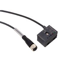
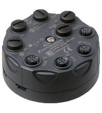
VBA-4A-G11-I/U-F
Цена по запросу
Параметры
| Выходы питания | Внутренний (от AS-i) |
|---|---|
| Выходы модуля | 4 |
| Стиль корпуса | G11 |
| Место монтажа | Полевой монтаж |
| Входы модуля | |
| Тип модуля | Аналоговые I/O |
| Подключение I/O | M12 |
| Тип узла | Стандартный узел |
Технические характеристики
The analog module VBA-4A-G11-I/U-F has four analog outputs. They can be configured either as current outputs (0 mA … 20 mA) or voltage outputs (0 V … 10 V). Automatic output detection allows outputs to operate as a current or voltage output, depending on the existing load. The outputs are configured as current outputs on delivery from the factory.
Power is supplied to the outputs through the yellow AS-Interface cable or auxiliary power, depending on the position of the DIP switch. Analog value conversion and data transfer are provided asynchronously according to AS-Interface profile 7.3. The rise time of the analog signals is approx. 2 ms.
If a current output has the analog value “0”, lead breakages are not monitored on the respective channel. In this case, peripheral faults are not signaled when there is no active connection to an actuator. If the internal “watchdog” monitoring function is enabled, the output signals are reset to zero if communication with the AS-Interface fails.
The G11 module with IP68/IP69K protection is particularly suitable for demanding field applictions. The connection to the actuators is established via M12 connectors. The module can be presddressed by connecting it to the handheld programming unit VBP-HH1 via the addressing socket. The connection to the AS-Interface transfer line is established using the AS-Interface flat cable.
Note:
A lead breakage at a current output, an output value outside the value range or an overload of the actuator supply is transmitted to the AS-Interface master via the ‘peripheral fault’ function. Communication via the AS-Interface continues.
| Описание продукта |
|---|
| Аналоговый модуль G11, 4 аналоговых выхода |
| Основные Характеристики | ||
|---|---|---|
| Node type | Стандартный узел | |
| Спецификация AS-интерфейса | В3.0 | |
| Требуемая спецификация шлюза | ≥ V2.1 | |
| Профиль | Профиль | |
| Код ввода-вывода | 7 | |
| Код ID | 3 | |
| Код ID1 | F | |
| Код ID2 | 6 | |
| UL File Number | E223772 | |
| Индикаторы/средства управления | ||
| Светодиод AS-i/НЕИСПРАВНОСТЬ | Status display; multi-colour LED Green: normal operation Red: communication fault Flashing yellow/red: address 0 Flashing green/red: peripheral fault |
|
| СВЕТОДИОД АНАЛОГОВЫЙ | Status of output signal; yellow LED Yellow: Output value within range Yellow flashing: lead breakage (on current output) or output value out of range |
|
| Светодиод AUX | ext. auxiliary voltage UAUX; dual LED green/red green: voltage OK red: reverse voltage |
|
| СВЕТОДИОД ВН/НАР | status display output supply; LED green green: output supply from AS-Interface off: output supply from auxiliary voltage |
|
| Электрические характеристики | ||
| Вспомогательное напряжение (выход) | 24 В DC ± 15 % PELV | |
| Номинальное рабочее напряжение | 26,5 … 31,6 В от AS-Interface | |
| Номинальный рабочий ток | ≤ 75 мА (без выходов) / макс. 200 мА | |
| Класс защиты | Класс защиты | |
| Защита от перегрузки | UAUX, Uin: Over voltage category III, safe isolated power supplies (PELV) | |
| Выход | ||
| Номер/Тип | 4 analog outputs Current: 0 … 20 mA Voltage: 0 … 10 V |
|
| Питание | from AS-Interface (switch position INT, default settings) or auxiliary voltage UEXT (switch position EXT) | |
| Нагрузка | voltage output: min. 1 kΩ current output: max. 600 Ω |
|
| Текущая нагрузочная способность | ≤ 120 mA (signal current + actuator supply) from AS-Interface; overload and short-circuit protected ≤ 700 mA (signal current + actuator supply) from external bulk power supply UAUX, overload and short-circuit protected |
|
| Разрешение | Voltage output: 3 mV Current output: 6 µA |
|
| Точность | 0,15 % от полной шкалы. | |
| Влияние температуры | 1 µA/K или 0,3 мВ/К | |
| Ток короткого замыкания | Выходное напряжение: макс. 22 мА | |
| Соответствие директивам | ||
| Электромагнитная совместимость | ||
| Directive 2014/30/EU | EN 62026-2:2013 | |
| Стандарты соответствия | ||
| Степень защиты | EN 60529:2000 | |
| Стандарт Fieldbus | EN 62026-2:2013 | |
| Излучаемые помехи | EN 61000-6-4:2007 | |
| AS-Интерфейс | EN 62026-2:2013 | |
| Помехоустойчивость | EN 61000-6-2:2005, EN 61326-1:2006, EN 62026-2:2013 | |
| Условия окружающей среды | ||
| Температура окружающей среды | -25 … 60 °C (-13 … 140 °F) | |
| Температура хранения | -25 … 85 °C (-13 … 185 °F) | |
| Относительная влажность | 85 %, без конденсации | |
| Климатические условия | Только для использования в помещении. | |
| Высота | ≤ 2000 м над уровнем моря | |
| Степень загрязнения | 3 | |
| Механические характеристики | ||
| Степень защиты | IP68 / IP69K | |
| Связь | AS-Interface/UAUX: cable piercing method, flat cable yellow/flat cable black Outputs: M12 round connector |
|
| Материал | ||
| Корпус | ПБТ ПК | |
| Крепежный винт | Нержавеющая сталь 1.4305 / AISI 303 | |
| Масса | 200 г | |
| Момент затяжки винтов корпуса | 1,8 Н·м | |
| Момент затяжки кабельного ввода | 0,4 Н·м | |
| Размеры | ||
| Высота | 35 мм | |
| Диаметр | 85 мм | |
| Монтаж | Монтажная плита | |